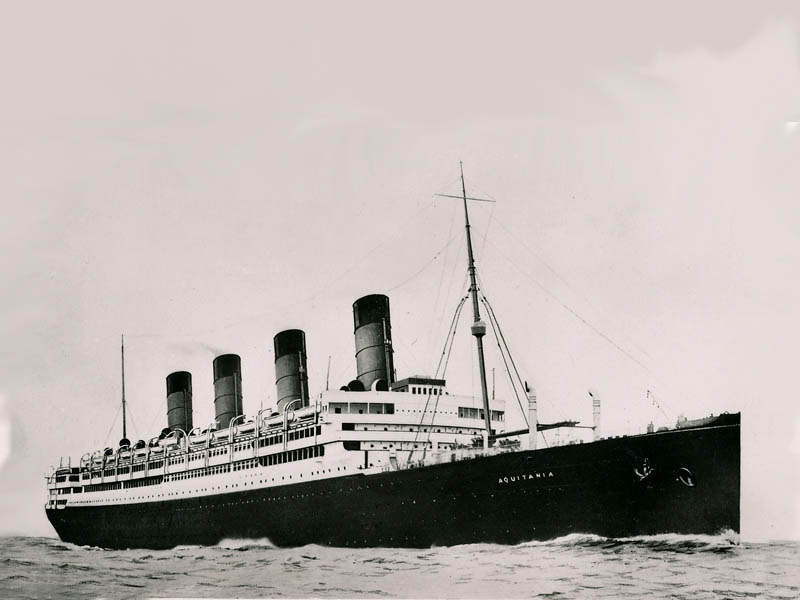
“Cunard Lines” R.M.S. Aquitania 1913 to 1950 - She also served in World War I & II.
Please Note: Firefox and some other Search Engines may not be suitable
Use Google Chrome for this Web Page to load perfectly!
![]()
Please Note: All ssMaritime and other related maritime
sites are 100% non-commercial and privately owned, thus ssmaritime is NOT
associated with any shipping company or any other organisation! Although the
author has worked and been involved in the passenger shipping industry for well
over 60 years, but due to his old age and poor health, he was forced to retire.
Yet, he has completed well over 1,365 Classic Liners, Passenger-Cargo Liners as
well as humble converted C3 converted Migrant Liners, which has transported
countless thousands folk to the new world, as well on vacations’. I trust
the features online will continue to provide Classic Liner and Ship enthusiasts
both the information they are seeking, but more so provide a great deal of
pleasure and relive many happy memories!
Please Note: Postcards, photographs & other images are either from the author’s private collection, unless stated otherwise.
A special thank
you to ssmaritime supporters
![]()
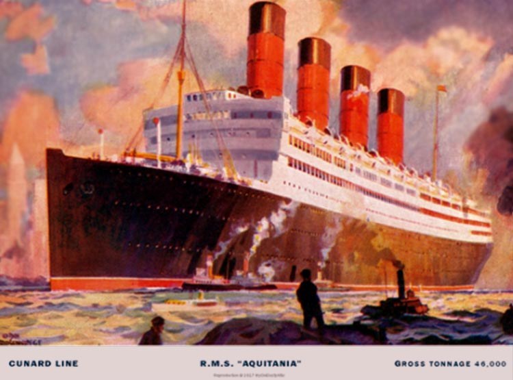
The superb stern view painting of the R.M.S. Aquitania’s which is after her 1920 refit
Page Three
Please Note:
This is an extensive multi page feature covering a very special liner, the
R.M.S. Aquitania, and if you have arrived at this page via a search engine, you
will find that this is Page Three of the “
Page One covers
the ship’s construction, her interiors to her maiden voyage and her early
Trans-Atlantic return voyages from Liverpool to
Page Two sees her requisitioned by the British Admiralty to enter World War One services, and this page will include the three roles she operated in during the Great War. 1. as an Armed Merchant Cruiser, 2; a Troop ship and 3; a Hospital ship. After the War she was refitted and returned to civil duties until World War Two when she became a Troop Ship once again. I will conclude Page Two with an extensive list of her specifications and other details, etc.
This Page covers every aspect regarding her massive power plant and other machinery, etc! Then there are several of her Deck Plans, followed by a Memorabilia section, and finally an extensive Ship’s Specification and detail section. Links to Pages One and Two are on the R.M.S. Aquitania Index at the bottom of the page.
A Brief Intro:
The “
Recently I located this incomplete item and it
needed some work still to be done to it. Thus I decided, although I had long
been retired that I would try and finally finish it, but I am sorry, this will
be my very last ssmaritime.com feature. I trust that you will enjoy it!
*************************
R.M.S. Aquitania’s Power Plant
Comprehensive Specifications & Details and Plans
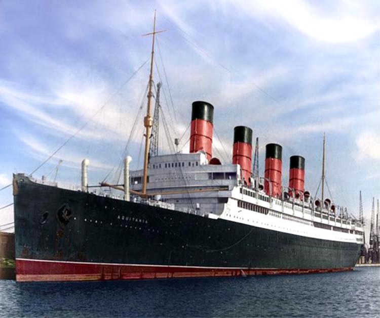
The R.M.S.
Aquitania is seen berthed in colour, but during her last days in 1949
Aquitania’s Power Plant
By
engineer,
Edited by ssmaritime.com
1. Overview of machinery spaces:
1.1 Boiler rooms.
The double-ended boilers are fired for transatlantic passages up to full speed and used for main propulsion, power generation, auxiliaries and many other services that require steam.
Each double-ended boiler has 4 furnaces served with coal from wing bunkers.
Combustion air for the boilers is provided by forced draught fans, as is usual for Cunard vessels.
1.2 Coal bunkers.
Coal bunkers are provided either side of the
stokehold furnaces in each boiler room to enable a ready supply of coal for the
trimmers and firemen to stoke the boilers. These bunkers form the
double side of the ship through all the boiler rooms in a similar way to the
Ash chutes are provided to discharge ash from the furnace bottoms overboard at regular intervals to keep the stokehold clear of ash whilst at sea. In port ash hoists are used to dispose of the ash to shore facilities.
The main steam pipes run the length of the boiler rooms to the bulkhead stops in the centre engine room for distribution to the engines and auxiliaries.

R.M.S. Aquitania’s stokehold prior to her oil conversion
1.3 Propulsion engines.
The propulsion system differs from the
The ship has a very comprehensive redundant system for running the turbines together or in isolation, but we will explain the normal triple-expansion arrangement.
Steam from the two main steam pipes running the length of the boiler rooms enters the engine rooms via bulkhead stop valves, operated by Brown’s engines and governors from the turbines. From the stop valves, the steam passes through a proprietary separator and via the manoeuvring valves into the ahead or astern hp turbine.
The exhaust from the hp turbine passes to the inlet of the lp turbine, which in turn exhausts to both the lp turbines.
Exhaust steam from the low-pressure turbines is directed to the vacuum condensers, situated in a further watertight compartment aft of the turbine room, where it is condensed into feed water and pumped back into the boilers.
Manoeuvring from ahead to astern is normally carried out using the lp ahead and astern turbines, with the hp and lp turbines used for working up to full speed. The turbines may be isolated in case of breakdown, though this bypassing is only used in an emergency.
Regulating valves, driven by worm and quadrant gear via spindles operated from the starting and manoeuvring platform, admit steam to the engines as required by the telegraph orders.
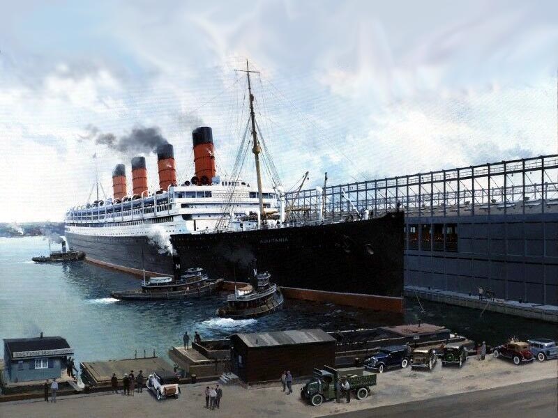
R.M.S.
Aquitania is seen at
2. Electrical power generation:
2.1 Main generating sets.
The vessel is fitted with four 400kW 225Vdc main turbo-generators driven by Parsons steam turbine prime movers at 1500rev/min. These sets are situated in a central station on H Deck, between Boiler Rooms 3 & 4. The main switchboard is situated at the fore end of the turbo-generator room.
Steam at a pressure of 150lb/in2 is fed to the turbines and exhaust steam is directed in port or at start up to the auxiliary condensers. At sea the exhaust steam is directed to the direct contact feed heaters to extract the remaining energy from the exhaust steam and deliver it to the feed heating system. This configuration gives a total installed power of 1.6MWdc, with three sets covering the full steaming load and one in stand-by.
2.2 Auxiliary/emergency generating set.
Whilst the vessel is – unlike the previous ships – fitted with an emergency generator, this is only a 30kW diesel generator and is provided solely for emergency lighting, wireless telegraphy etc. It cannot run a FD Fan (50hp, or 37kW), so we still need to start using shore power. As it is not possible to cold start with the machine, it is open to conjecture why it is fitted. If all the boilers and main generator sets are out of action at sea (most unlikely with the amount of redundancy of the systems) it should have at minimum been able to power the emergency systems plus any one FD Fan, by fitting two such generators instead of one. In a Titanic situation it would at least allow the engineers to escape the doomed vessel!
2.3 Firing up the boilers.
The engineers start the required forced draught fans on the shore power supply. Assuming that for a main generator to run we need at least all the fires in one boiler room lit, one FD fan is started to supply the furnaces in one of the main boiler rooms. The firemen are set to work in this boiler room to lay fires in all required furnaces. Once lit, the boiler draft is adjusted by dampers and the fires start to heat the water in the fire-tube boilers. Water-tube boilers are much more efficient and faster starting than fire-tube, but hadn’t been invented at this time. It would take around 12 hours to raise steam to manoeuvring pressure.
It’s now 12 hours on, and we have around 190lb/in2 at the main stops to the main steam lines to the engine rooms. The main stop valves of the boilers are cracked open to the main steam pipe and the piping and valve drains opened to clear the lines of condensate, which can damage reciprocating and turbine machinery. The remaining boilers are banked until main power is available.
3. Starting the generators:
3.1 Auxiliary seawater pumps and condensers.
In order to start a turbo-generator, the exhaust steam from the engines is directed to an auxiliary condenser, of which there are two, one in each of the watertight wing engine rooms situated either side of the centre turbine room. The seawater passing through this condenser condenses the exhaust steam into water, thereby dropping its pressure. Without this the engine would trip on high exhaust backpressure, as the exhaust steam has nowhere to go. In addition the condensers are supplied with an auxiliary air pump (or vacuum pump) to increase the vacuum in order to drop the exhaust steam pressure further.
The auxiliary seawater pumps are steam driven and situated in the same room as the auxiliary condensers.
With the drains open, steam is admitted to the pump, which circulates seawater through the auxiliary condenser to overboard. In the same way the auxiliary air pump is started in order to draw a vacuum. We are now ready to start a generator.
3.2 Starting the main generators.
As we will soon be consuming steam, we will also need to be able to start a main feed pump to supply the boilers with feed water as required.
The generator bearings are forced lube type, so first we start a LO pump (again steam driven, as are nearly all the engine room auxiliaries) in the usual way.
After warming through the generator steam lines and opening the engine exhaust to the auxiliary condenser, the first and subsequent generators are warmed through and run up to a speed of 1500rev/min.
On the main switchboard (of which there are two, joined by a bus-tie breaker), the breaker is closed for the generator in question and the shunt field regulator adjusted to give mains 225Vdc voltage. There is no need to synchronise dc machinery unlike alternating current machines. Once the generator has settled down on the board, the shore breaker is opened to avoid back-feeding the shore supply as the main generator loads up.
We can now put the other generators on the board as required. We are up and running and can connect other feeders via the main switchboard distribution.
As you can see, this is quite a long job compared to a modern diesel powered ship (though steamships still take some time). A blackout on a modern motor ship can be restored within a few minutes.
3.3 Starting main engines.
We now have power for firing all the boilers necessary for starting the main engines and getting the engine rooms ready for sea.
First we have to get the propulsion exhaust steam system arranged in a similar way to that of the generators but, in the case of the main engines, the auxiliary condenser is nowhere near big enough to handle the exhaust from the propulsion engines.
For this we need to draw a vacuum on the main condensers of which there are two, situated in a watertight condenser room aft of the low-pressure turbine room.
3.4 Main seawater pumps.
As with the auxiliary condenser, we need seawater to condense the steam and drop its pressure to avoid exhaust backpressure on the engines. These are pretty huge and are driven by compound steam engines. There are two pumps per condenser (total of four) arranged adjacent to the condensers in the condenser room.
As with all steam engines, these are first warmed through with the drains open, then slowly started up until they are at full revs. Once the pumps are started, seawater passes through the condensers and discharges overboard – that’s the large discharge that can be seen on any steamship up to the present day.
3.5 Main dual dry/wet-air pumps.
The air pumps (called vacuum pumps these days) evacuate air and water vapour from the condensers and draw a vacuum in so doing. This improves the exhaust flow from the engines and also extracts the maximum energy from the steam. They are situated aft of the main condensers and are of course steam driven. They are started in the usual way, and left to draw a vacuum on the condensers, usually around 28.5in with an atmospheric pressure of 30in. Water from the wet-air pumps is returned to the hot-well tank under the condensers, as is air from the dry-air pumps.
3.6 Main generators.
Now that the steam and feed system is up and running, we can extract the energy from the main generator exhaust by redirecting it from the auxiliary condenser to the contact/direct feed heaters, through which the condensate from the feed tank passes via the hot-well pumps (see later) to mix with the generator exhaust steam. This imparts heat to the feed water to avoid wasting the energy from the generator exhaust.
3.7 Main engines.
By this time the engineers (we assume we are not doing this on our own) will have engaged the electric turning gear motors on all four shafts, as well as starting the turbine forced lube oil pumps (steam driven). The engines are kept turning until required for use, whence the gear is withdrawn to avoid damage to it in the event of starting a turbine with it engaged. Gland steam is assumed to have been fitted (no mention in the Engineer & Shipbuilder reprint I have) and will be started up to extract leakage steam from the turbine shaft glands, and condense it back to the hot-well drains.
The turbines are kept warmed through ready for manoeuvring and working up to speed on passage, with manoeuvring steam admitted to the hp turbine with the drains full open and the exhaust open to the lp turbine. In series, the exhaust steam from lp turbine exhausts via two branches into the lp turbine sets. At first the main steam stop valves are cracked open until everything is warmed through, whence they can be fully opened.
Once the turbine drains are emitting steam, we can call the bridge and ask if the propellers are clear for a slow turn ahead and astern on all shafts. Once this is given, the hp turbine manoeuvring valve is set to the ‘ahead’ position (which isolates the astern turbines) and the main steam regulating control valve cracked open at the starting platform at the forward end of the lp turbine room. Each engine turns ahead at low revs. After a few turns of the shafts ahead the regulating valve is closed and the manoeuvring valve set to the astern position to feed steam to the astern turbines on each shaft. Again the regulating valve is cracked open and the astern hp turbine turns, with its exhaust to the lp astern turbine and the lp exhaust to the lp astern turbines. The shafts turn astern for a few revs at low speed.
We are about ready to go, and test the communications between the engine room, boiler rooms and bridge so that we are ready for sea service. Around the same time an engineer is dispatched to the steering engine room to warm through the steering engines and test the rudder from amidships to 30 degrees port, back to 30 degrees starboard then returning to amidships.

Here we
see
3.8 The feed system.
Steam from the condensers that has condensed into the hot-wells under the condensers is returned to the boilers via two feed heaters using the sets of hot-well pumps located under the main condensers. These pumps deliver the condensate to the surface feed heaters located high in the engine room above the lp turbines. These heaters are fed with exhaust steam from the auxiliaries (the pumps mentioned above, such as seawater, air pumps, lube oil pumps etc.) and this steam heats the feed-water passing through the shell and tube heating elements.
From the outlet of the surface heaters the
feed water is passed to the second of the two feed heaters, which is
a direct/contact heater where the water comes directly in contact
with exhaust steam from the main generating sets. These heaters are
also situated high in the engine room above the lp
turbines and act as a desecrator once the air vent at the top of the heater is
opened up to the main condenser to extract undesirable gases (CO2 and O2),
which can cause corrosion problems in the boilers. In this heater
the generator exhaust steam condenses in contact with the boiler feed water
stream from the hot-well pumps and is then extracted under gravity by the main
feed pumps and sent to the boiler distribution mains as required.
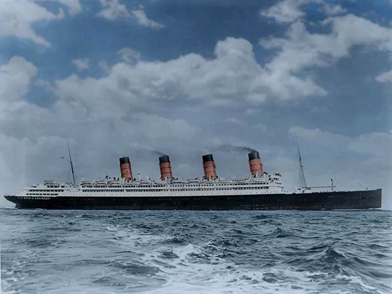
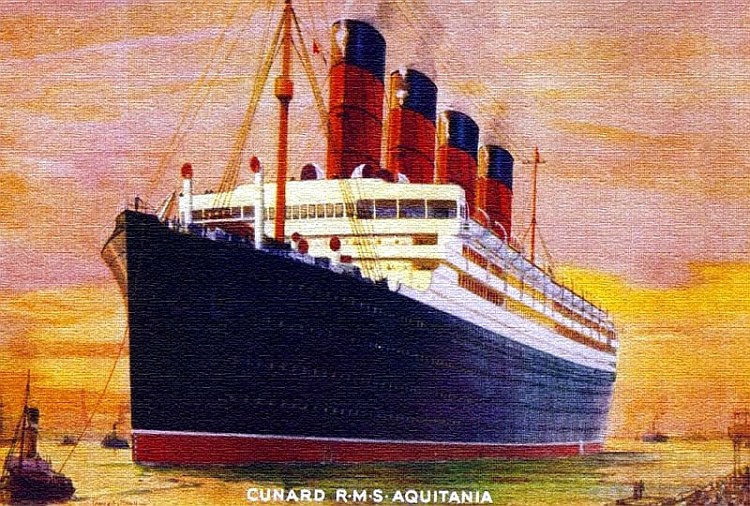
A splendid view of the R.M.S. Aquitania at sea in colour
Taken from a
postcard and colourised - kindly provided by
4 Getting under way:
In response to the bridge signals on the engine room telegraphs, the ahead/astern turbine sets are manoeuvred accordingly as above and the ship departs her berth and heads for the open sea.
4.1 High-pressure and intermediate-pressure
turbines.
Once the ship is up to full ahead, and prior to full away, the steam is now passing from the boilers to the main steam lines, through the hp turbine, into the lp turbine, then the lp turbines and finally exhausting to the condensers, from where it is returned to the boilers as above in a closed feed cycle. Full power can now be worked up once full-away is rung on the telegraphs.
We’re done, we’ve been down below on a coal-burner for over 12 hours, and it’s time to go to bed.
5 Coal-firing vs
oil-firing:
Coal-firing was a dirty, messy, labour-intensive way to feed a furnace. As well as bunkering and firing the boilers, disposal of the ash was an additional burden on the stokehold staff. “Coaling ship” was an “all hands” task where everyone turned to in order to fill the coal bunkers via coaling ports in the side of the ship.
Oil-burning on the other hand is far less labour-intensive, with the bunkering taking place via a hose from a bunker barge in to the same bunkers as the coal was previously.
A coal-fired ship needed some 250 stokehold
staff to fire and tend the boilers, whereas ships like

There were
filthy conditions in a coal-fired stokehold

A clean and tidy stokehold after her conversion to oil
From the pictures above, compared to the filthy conditions in a coal-fired ship, can be seen the huge improvement in working conditions once the stokehold had been converted to oil firing.
In addition, firing on oil was far more
efficient, and the power output of
One procedure that didn’t really improve was the length of time taken to raise steam in fire-tube boilers, and it was some years before the next major trans-Atlantic steamship was built using water-tube boilers. This was the Empress of Britain, which will be discussed in a further document on starting these large liners from cold.
Profile of Boiler Rooms:

On the view in Figure 9 can be seen the extent of boiler rooms 2, 3 and 4, with a hint of Boiler Room 1 at the fore ends. The boilers are installed 6 to a room, 3 abreast.
Uptakes:
The uptakes can clearly be seen, illustrating that all four funnels on this vessel served the boilers (unlike the Titanic, whose aft funnel was a ventilation shaft.
Turbo-generator Flat:
Between frames 124 and 133 are the 4 main generators and switchboard.
Main steam lines, FD fans and escape ladders
On the profile view, note the main steam lines running the length of the ship above the boilers and the forced draft fans mounted on the deck above. No. 1 & 2 boiler rooms feed one steam line, 3 & 4 the other. The line size changes towards the forward engine room bulkhead as the steam volume increases with more boilers on line.
Also note the vertical ladders the same as the Titanic where the stokers can get out of the stokehold if the watertight doors are closed.

R.M.S. Aquitania plans of the watertight subdivisions in the ship

R.M.S. Aquitania Section of boiler room at Fr.146
In this section can be seen the arrangement of the boilers athwart ships in threes. Each double-ended boiler has 4 furnaces at each end, or 8 furnaces per boiler. Note the boiler seating’s – not designed to hold the boilers in place if the ship takes a plunge to the bottom. The fine line just above the bottom of the boiler shell is the floor plating. This is fitted accurately into the stokehold to stop ash from dropping through and clogging the space below which, whilst it looks empty, is fairly full of piping.
Ash from the furnaces is shovelled into holes covered by gratings, which are the ash chutes. The ash hoists take up ash, and a jet of water takes the ash over the side as shown in the pipes going outboard on the above drawing.
Also shown are the boiler main stops feeding the main steam lines running through the boiler rooms from forward to aft.
Plan and elevation of machinery rooms:
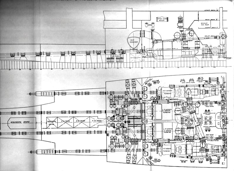
R.M.S. Aquitania Plan and Elevation of machinery space
The views in Figure 12 and Figure 13 show the forward engine room bulkhead on which are the bulkhead stops for the two main steam lines exiting from No4 boiler room. The bulkhead stops are actuated by Brown’s steam engines, as they are too large to manually operate. The engine over speed governor can act on these valves and shut off the steam in the event of over speed. Also shown are the direct steam lines to the wing turbines and the large steam separators.
R.M.S. Aquitania Section at Fr 10 looking forward
The four propulsion turbines are shown; the hp turbine in the port watertight compartment, the lp turbine in the starboard watertight compartment and the two lp turbines in the centre watertight compartment. The steam lines interconnecting the turbines in series are also shown.
Steam lines:
The steam, after passing though a strainer to remove particles, is directed to the hp turbine via the pipe passing through the watertight longitudinal bulkhead. The ahead steam pipe of 32” bore is shown entering the turbine on the centreline, at Fr. 102. The hp astern steam line is shown outboard of the turbine passing aft to the hp astern turbine at Fr. 92.
The hp turbine exhaust is directed to the lp turbine inlet via the large changeover valve (used for isolation purposes) and the 53” pipe routed across the space to the lp turbine inlet at Fr. 102. Note that there is also a 25” steam line from the bulkhead stops direct to the lp turbine when the hp turbine is isolated.
The lp turbine exhaust is led via the 90” bore line to the 66” inlets on the two lp turbines.
After passing through the lp turbines, the steam exits to the condensers via the large rectangular exhaust ports shown on the top of the turbine casings at Fr.87.5.
When running astern on the hp and lp astern turbines, these units exhaust direct into the lp astern turbines on each side. In the astern case it seems from the drawings that the hp/lp and lp turbines are in compound arrangement and not triple-expansion. The hp and lp astern turbines are therefore controlled independently via the astern regulating valves for each set shown on the forward engine room bulkhead.
The starting platform from where the engines are driven ahead and astern is located at the forward end of the lp engine room, arranged on the centreline under the bulkhead stops. The starting wheels comprise a large outer wheel for the bulkhead stops, and a smaller inner wheel for the manoeuvring valves. The levers for controlling the turbine drains and sluice valves are close by.
Turbine isolation:
The various changeover valves and bypass lines show how the turbines can be arranged for maximum redundancy. However, operating on a wing shaft can only be carried out using the two shafts on that particular side of the ship. The large shut-off valve on the centreline isolates the hp and lp turbines from each other such that the hp and lp (P) run together, and/or the lp and lp (S) run together. The changeover valve isolates the lp turbine from the hp turbine, and allows the hp turbine to exhaust into the port lp turbine inlet.
Main manoeuvring valves:
Arranged on the forward bulkhead can be seen the outlines of the various manoeuvring valves that direct steam into the turbine inlets.
Feed water pumps and forced lube oil pumps:
In the space between the starting platform and the forward end of the lp engines are arranged the main feed-water pumps. These pumps draw from the direct/contact feed heater mounted on the flat above the turbines, and is shown on the elevation at Fr.95.
The forced LO pumps are also shown in the same space, as are the large oil coolers further aft.
Auxiliary equipment:
A set of evaporator machinery for producing fresh water is installed in each wing turbine room, as are various other water and service pumps.
The auxiliary condensers and associated seawater pumps and air pumps are arranged at the forward end of the wing turbines rooms. The Stone-Lloyd pumps are shown located under the shutoff valve in the centre of the lp turbine room, and are for operating the watertight doors.
Main condenser rooms:
In the main condenser rooms are installed the main condensers, separated by a centreline watertight bulkhead. Mounted under the condensers are the hot-wells for collecting the condensed steam, and the hot-well pumps, which pump the condensate into the feed system, are shown just forward on the centreline.
Also in the condenser rooms are the main seawater circulating pumps – 2 each side – and the dual air pumps for creating and maintaining vacuum on the condensers.
Shafting and propellers:
In the watertight compartment aft of the condenser rooms and mounted within the double bottom are various water tanks. From the thrust bearings mounted at the aft end of the lp turbines (the engines which are coupled to the centre shafts) the two propulsion shafts are arranged in the shaft tunnels and exit the ship via the stern tubes. There are several intermediate bearings (Plummer Blocks) along the length of the shafting which are splash lubricated.
On the plans above can be seen the subdivision of spaces within the ship. Unlike Titanic, the watertight bulkheads are not open at the top, but are connected to watertight decks.
The boiler rooms are subdivided by longitudinal (the watertight bunkers) and transverse bulkheads, which separate each set of 6 boilers from their neighbours.
Anti-rolling tanks are fitted outboard of Boiler Room 3, but it is not known whether these worked or not.

R.M.S. Aquitania Section through Turbine Rooms at Fr.98, looking Aft

R.M.S. Aquitania Section at Fr.109, looking Aft
************************
Aquitania’s Memorabilia Section
Including Menus & Events
I have a number of excellent items of memorabilia in my collection, and below are just some of them, enjoy!
A
Cunard-White Star Post card of the
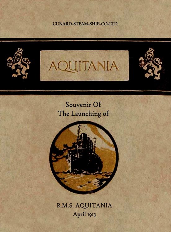
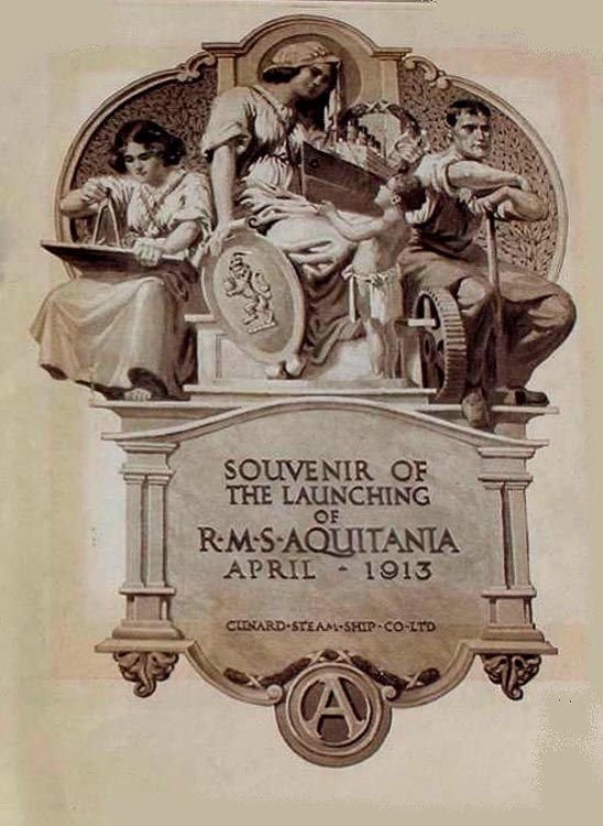
Above & below: Here we see the official Cunard Booklet given to the official party at her Launching
Above we
see the cover and below a title page inside
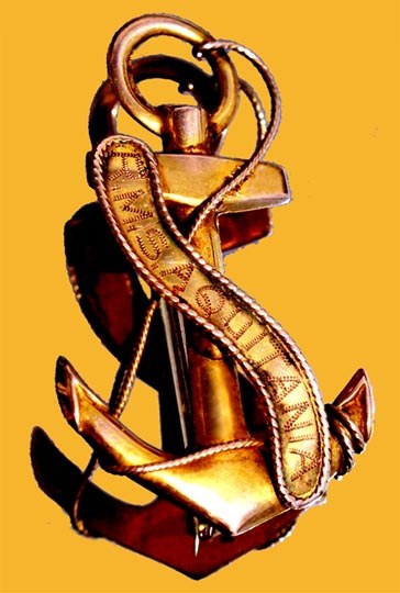
Above we see a very special R.M.S. Aquitania souvenir Anchor Brooch that was only available in First Class. Why? Well it was the cost of this luxury item, for this brooch is made from solid gold and it was certainly not plated!
![]()
Cunard-White
Star Line R.M.S. Aquitania hand painted solid gold badge also purchased onboard

A souvenir
dish available for sale in all classes
Menus and a Shipboard Events Programme

Above & below: Here is a First Class Luncheon Menu dated February 23, 1937
The cover
is seen above and the menu below

A First
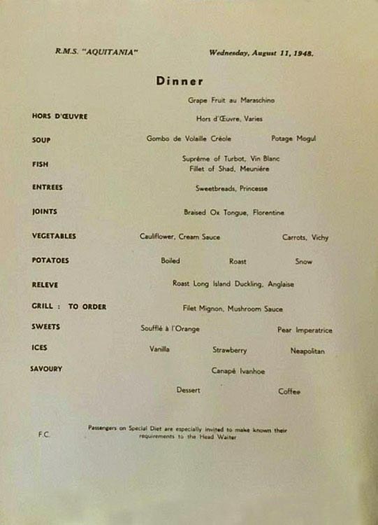
Class Dinner Menu dated August 11, 1948

This is a Second Class Breakfast menu dated November 26, 1948
After this
voyage to

Above & below: This is a Third Class “Easter” Dinner menu dated April 9, 1939
The Cover
is above & the Menu is below


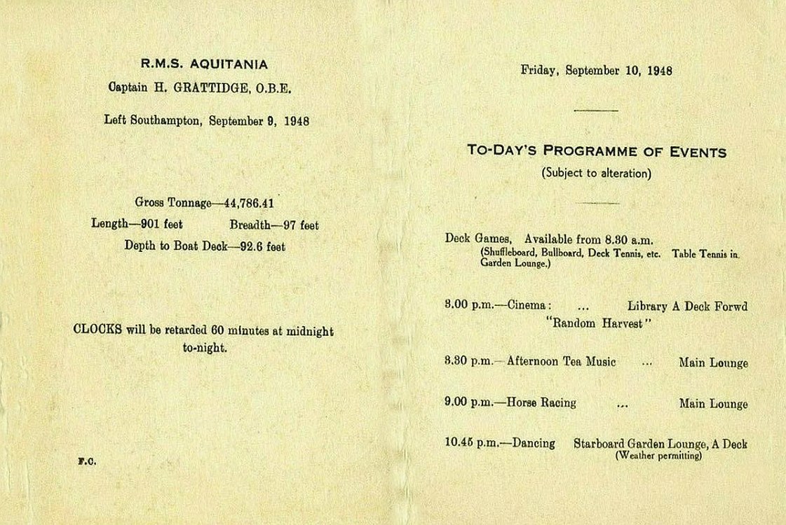
Above & below: Here we see the First Class “Today’s Programme of Events” dated September 10, 1948
The Cover
is above & the Programme is below

And here
is a Second Class “Cabaret Programme” and Dinner Menu dated
September 19, 1929
R.M.S.
Aquitania is seen in a floating dry-dock in
************************
Deck Plans
Sadly there are not many good deck plans available, thus I have one large plan covering Boat Deck and the Promenade (A) Deck, you can click on the image or the link below it and a much larger image will appear.
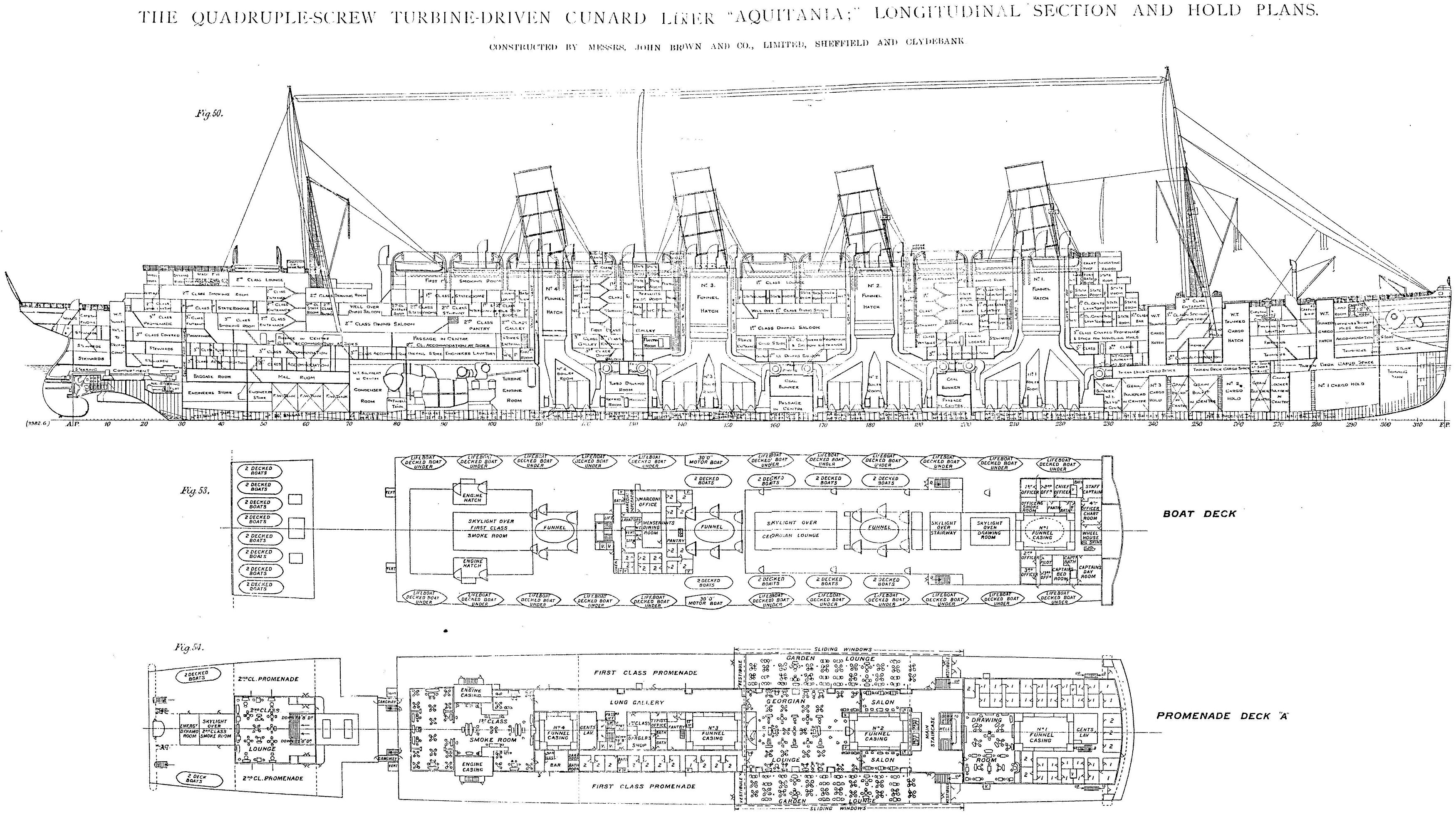
View the
large plan online - Click HERE
The next plan is a full colour plan published by Cunard just for her cruises duties.

*************************
She is seen her just after her 1919/20 refit
Comprehensive Specifications and Details:
Names & prefixes: R.M.S. Aquitania 1913 - 1914.
. H.M.A.M.C. Aquitania Aug 1914 - Sep 1914.
. H.M.T. Aquitania
. H.M.H.S.
Aquitania 1915 -
1916.
. R.M.S. Aquitania 1916 - 1950.
. H.M.T. Aquitania 1939 - 1948.
. R.M.S. Aquitania 1948 - 1950.
Type of ship: Passenger / Troop Ship.
Vessel description: Steel Screw Steamer.
Official No: 135583.
IMO No: 1135583.
Owners: 1914-1934; Cunard Steam Ship Co. Ltd,
. 1934-1949;
Cunard-White Star Line Ltd.,
. 1949-1950; Cunard Line.
Ordered: December 8, 1910.
Builder: John Brown & Co Ltd.,
Yard: 409.
Laid down: June 5, 1911.
Launched: April 21, 1913 - by
Completed: May 12, 1914.
Delivered: May 24, 1914.
Maiden Voyage: May 30, 1914.
Service: Liverpool-
.
. Southampton-Halifax (1948–1950).
Tonnage: 45,647 GRT, 21,993 NRT, 11,280 DWT.
Length: 901 ft - 275.2 m - 1931 to 1947.
Breadth: 97.0 ft - 29.6 m.
Depth: 49.7 ft - 15.1 m.
Draft”: 36.0 ft - 11 m.
Engine details: 4 Parsons direct drive steam turbines combining 3 of high pressure and 1 low pressure.
Engine built by: John
Brown & Co Ltd.,
Boilers: 21 double ended coal fired boilers.
. Converted to oil burning in 1919-20 by
Horse Power: 62,000 HP.
Shafts: 4.
Propellers: Quadruple Screws.
Speed: 23 knots service speed, 25.1 knots maximum.
Funnels: 4.
Masts: 2.
Accommodations: 1914 to 1926 - 618 passengers in First, 614 in Second & 2,004 in Third Class.
. 1926 to 1950 - 610 passengers in First , 950 in Second & 640 in Tourist Class.
Troop Capacity: from 5,000 to 6,400.
Captains:
.
.
.
.
Crew: 972 up to 1,200.
. 850 from 1926.
Her Final Days:
December 1949: Laid
up on the
February 13, 1950: Sold
to “British Iron & Steel Corp. Ltd”,
February 18, 1950: The Cunard flag is taken down and she is transferred to the breakers.
February 19, 1950: “Aquitania
departs
February 21, 1950: Arrived at the Faslane breakers yard.
October 12, 1950: Whilst being broken up at Faslane she was swept by fire.
Additional Information:
Passenger Voyages: 443 Trans-Atlantic voyages.
. She sailed over 3,000,000 miles during her career carrying over 1.2 million passengers.
WW 1: 1. Armed Merchant Cruiser
Armaments: 10 x 6”/45 (15,2 cm single mounted, with a range of 14,600 yards @ 20°(8.2 miles.
. 2. A hospital ship she transported over 25,000 injured troops.
. 3. A troopship she carried around 60,000 soldiers.
WW2: She sailed over 500,000 miles transporting over 400,000 troops, etc.
Armaments: 1 x 6” single mount with a range of 14,600 yards @ 20°(8.2 miles.
. 3 x 5” single mount & a numb rod 20mm and 40mm Single mounts, the 40mm range of 10,750 yards @ 45°, AA ceiling of 23,500’.
Note: The “
*************************
Remembering the Grandiose & Luxurious …
R.M.S. Aquitania
A view of R.M.S. Aquitania just after her 1920 refit
R.M.S.
Aquitania’s Index
From Concept, Construction,
Interior & exterior Photo Album,
her Maiden Voyage and pre WW1
services.
Aquitania WW1, Civil service & WW2, with her
final days.
*************************
“Blue Water Liners sailing to the distant shores.
I watched them come, I watched them go and I watched them die.”

Featuring over 1,365 Classic Passenger Liners, Passenger-Cargo Liners & Classic Cruise Ships!
Or ENTER HERE
For interest:
Sadly an email service to ssMaritime is no longer available, due to the
author’s old age and chronic illness as well as being disabled, etc. In
the past ssMaritime received well over 120 emails per day, but
**************
ssMaritime.com & ssMaritime.net
Where the ships of the past make history & the 1914 built M.S. Doulos Story.
The Author has been in Passenger Shipping & the Cruise Industry for well over 60 years
In addition he was the founder of “Save the Classic Liners Campaign” in 1990.
Please Note: ssmaritime and associated sites
are 100% non-commercial and the author seeks no
funding or favours of any shape or form, never have and never will!
Photographs
on ssmaritime and associate pages are by; the author or from the author’s
private collection. In addition there are some images that have been provided
by Shipping Companies and private photographers or collectors. Credit is given
to all contributors. However, there are some photographs provided to me without
details regarding the photographer/owner concerned.
This notice
covers all pages; although,
and I have done my best to ensure that all photographs are duly credited
and that this notice is displaced on each page, that is, when a page is updated!
ssMaritime is owned & © Copyright by